

Overhead Arm Support
Overhead Arm Support Training
Codes: AM4000 · AM4100How to use Overhead Arm Support
Choosing the right Overhead Arm Support device
When choosing the right device, consider patient weight and bore size compatibility.
The standard AM4000 is designed for patients weighing 47 - 135 kg, and for CT/MRI bore size ≥ 700 mm.
The small AM4100 is designed for patients weighing 13 - 47 kg, and for CT/MRI bore size ≥ 600 mm.
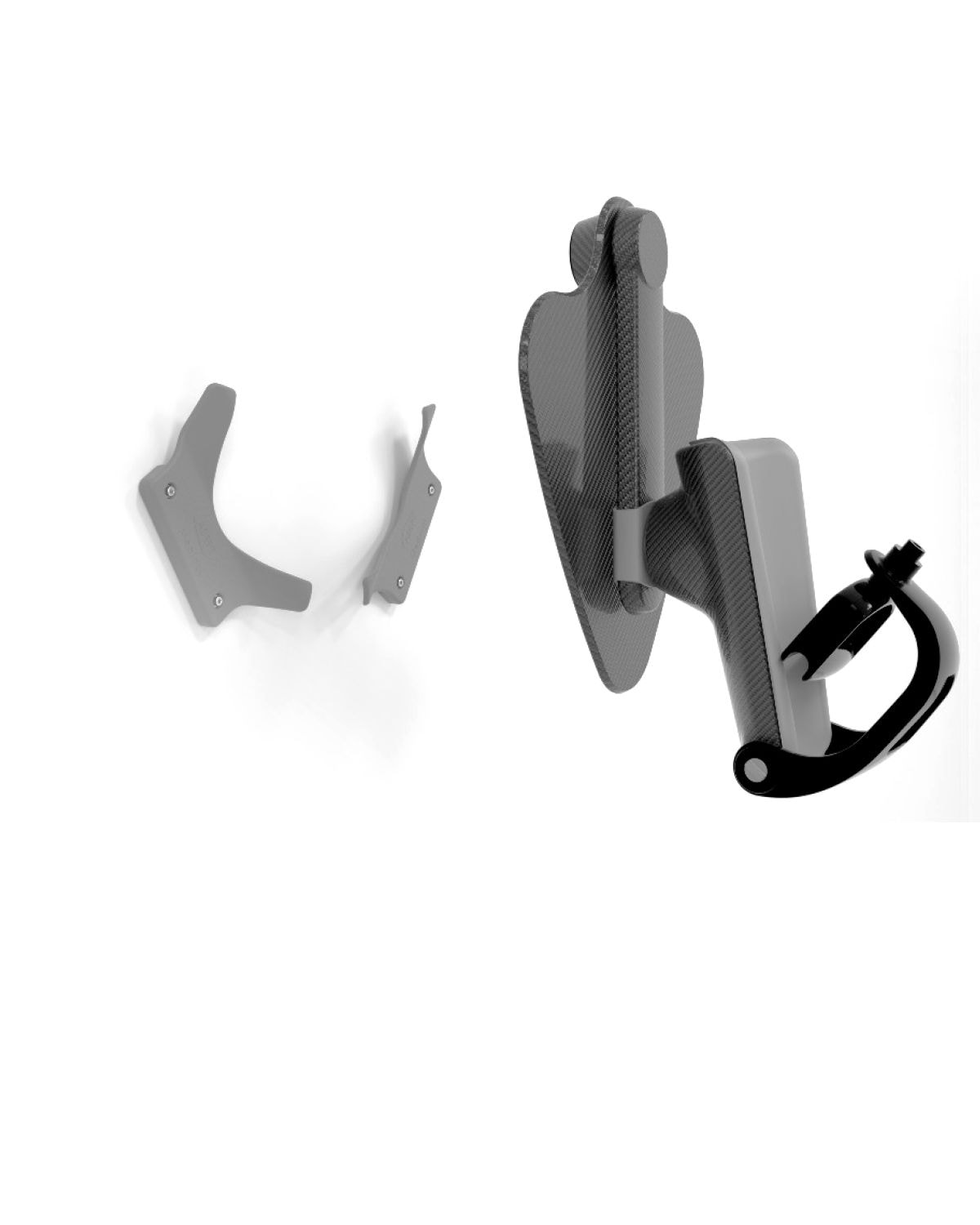
How to assemble the Overhead Arm Support
Insert the bottom of Locking Leg into the base board with the blue locking Lever facing the back. Ensure it clicks into place. Then gently push the Armrest Wing (Small) to the top of the locking leg, the wings facing away from the blue locking Lever.
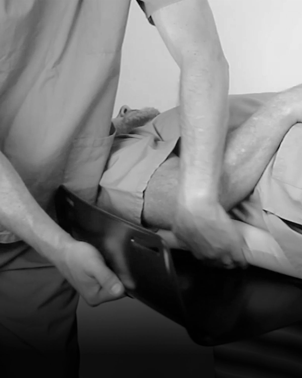
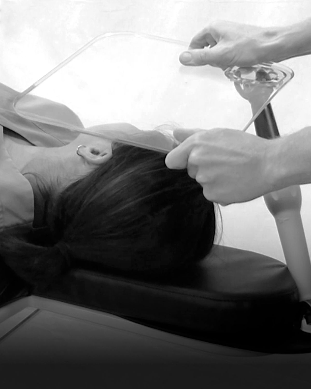
How to set up the Overhead Arm Support base board
You can insert the base board between the mattress and image table surface or above the mattress under a pillow, depending on your requirement.
> If under the mattress: ensure the locking leg sits flush against the mattress edge
> If above the mattress: ensure the daggerboard is fully under the pillow
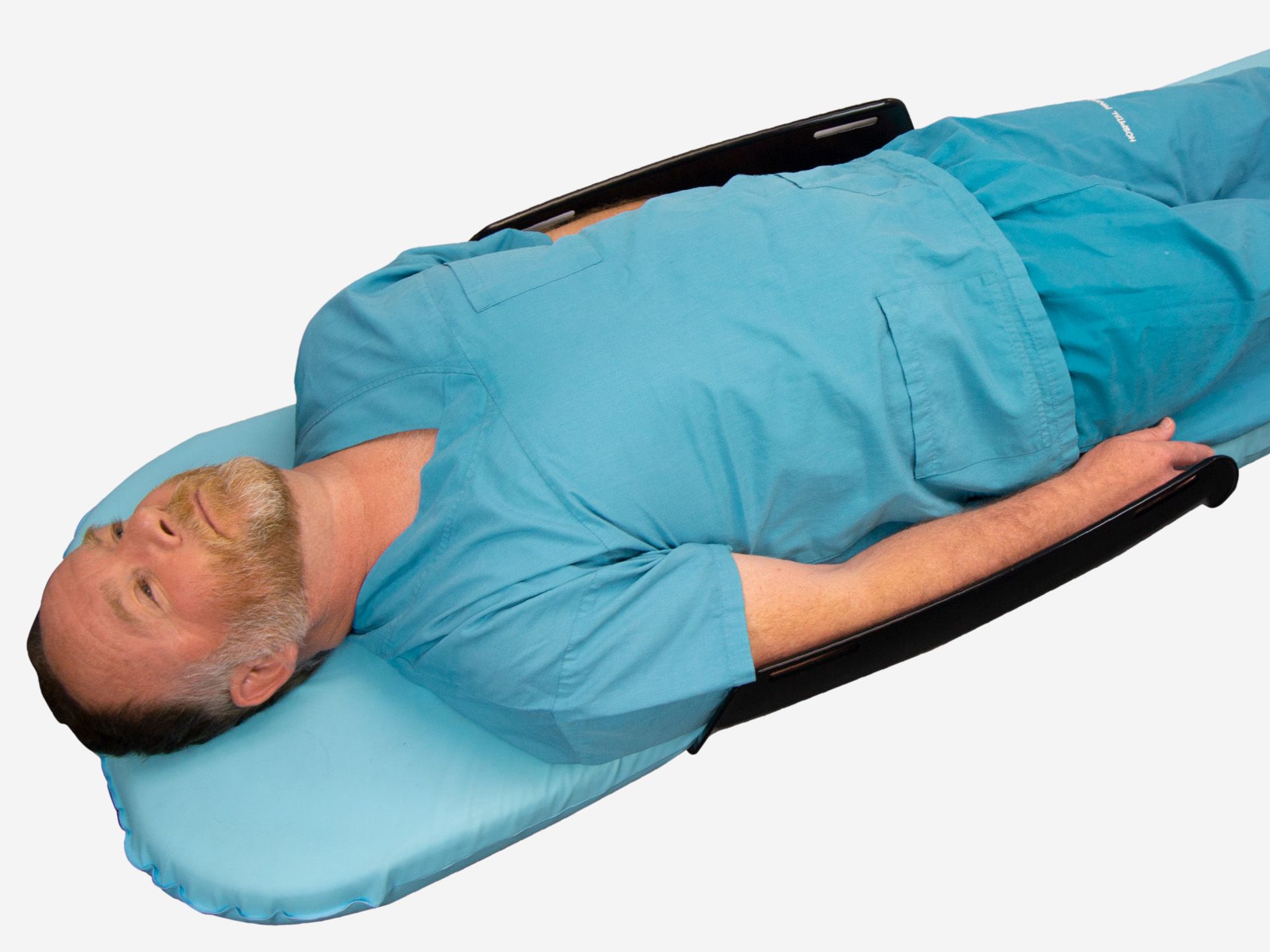
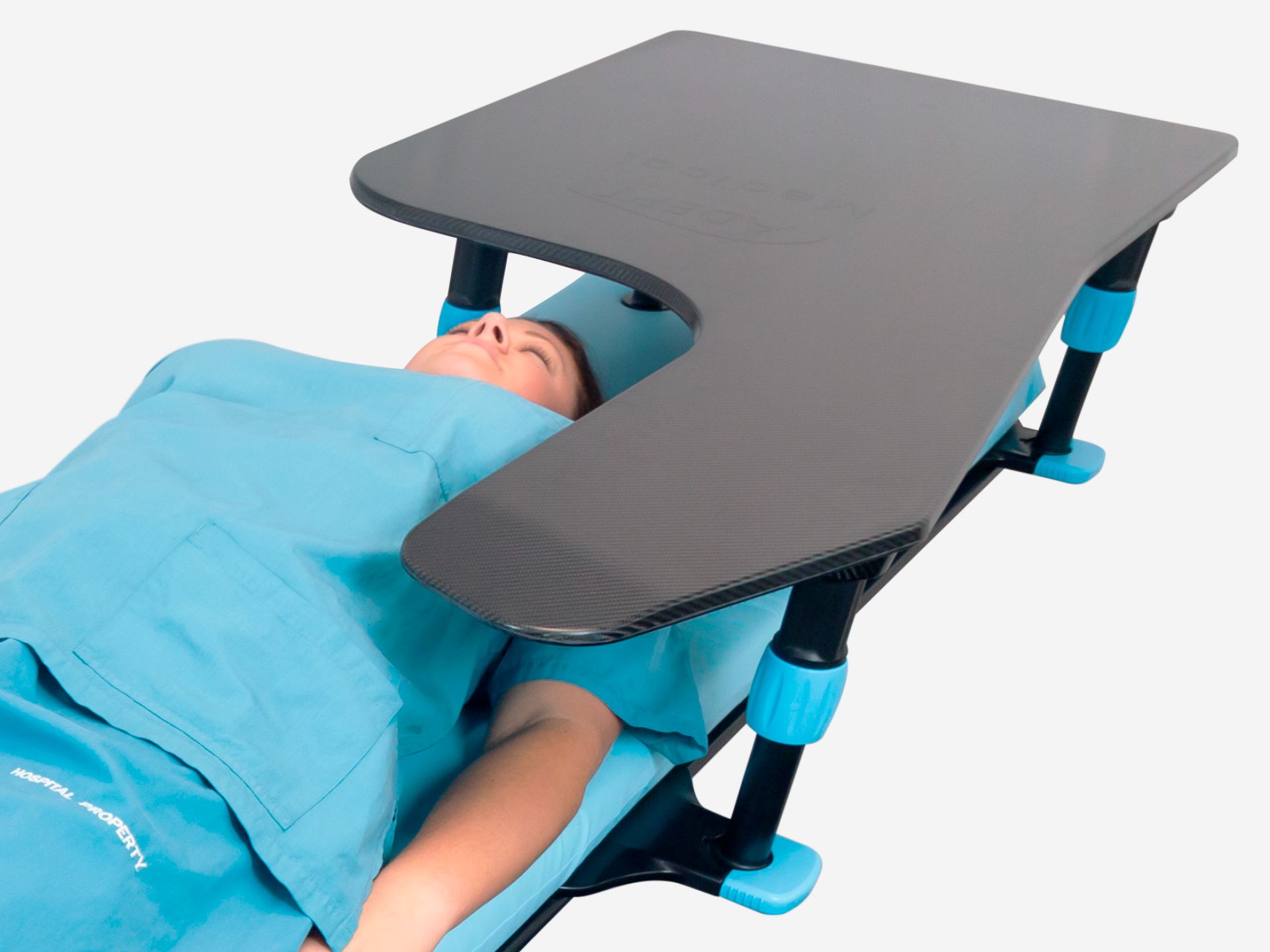
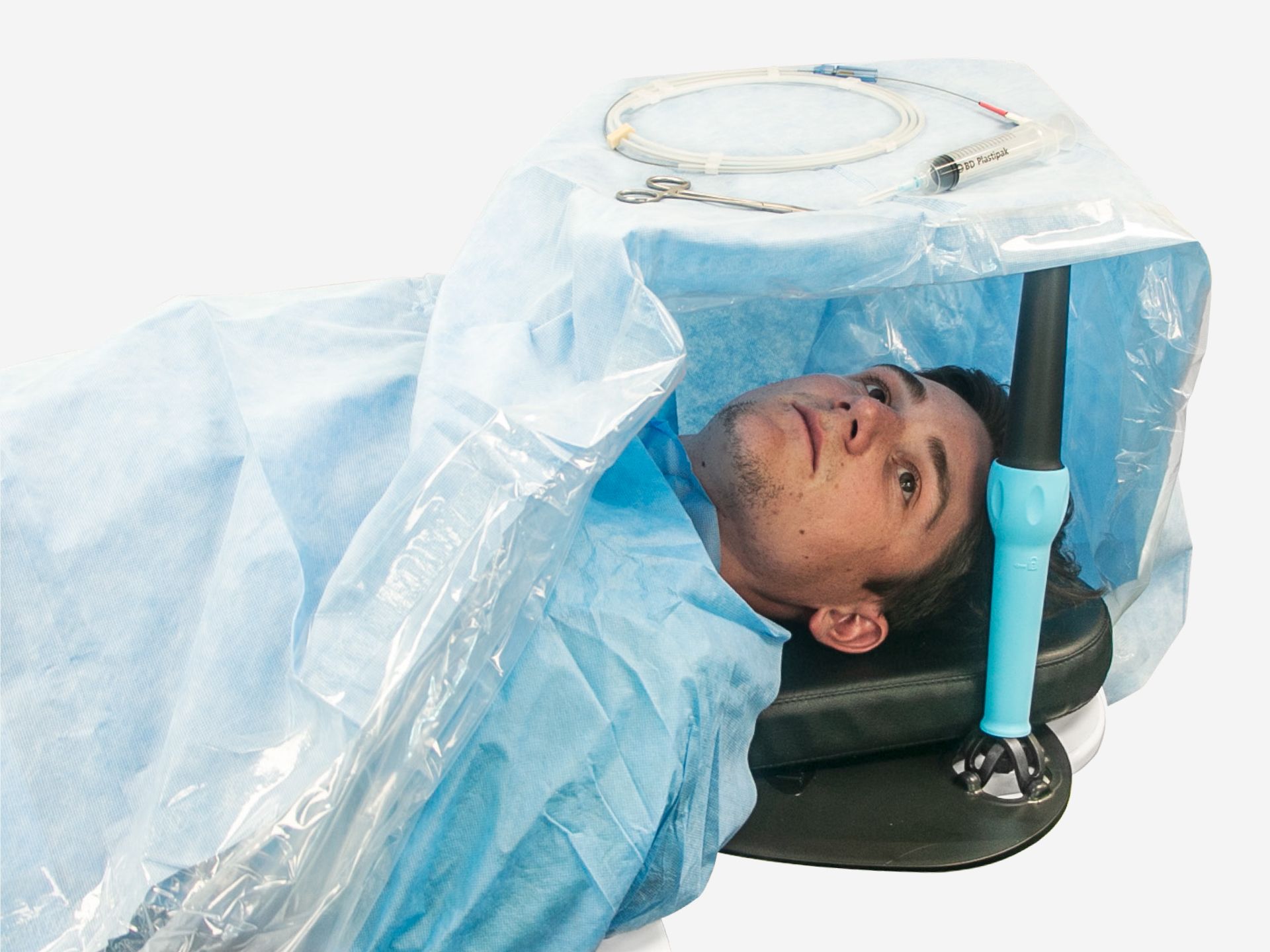
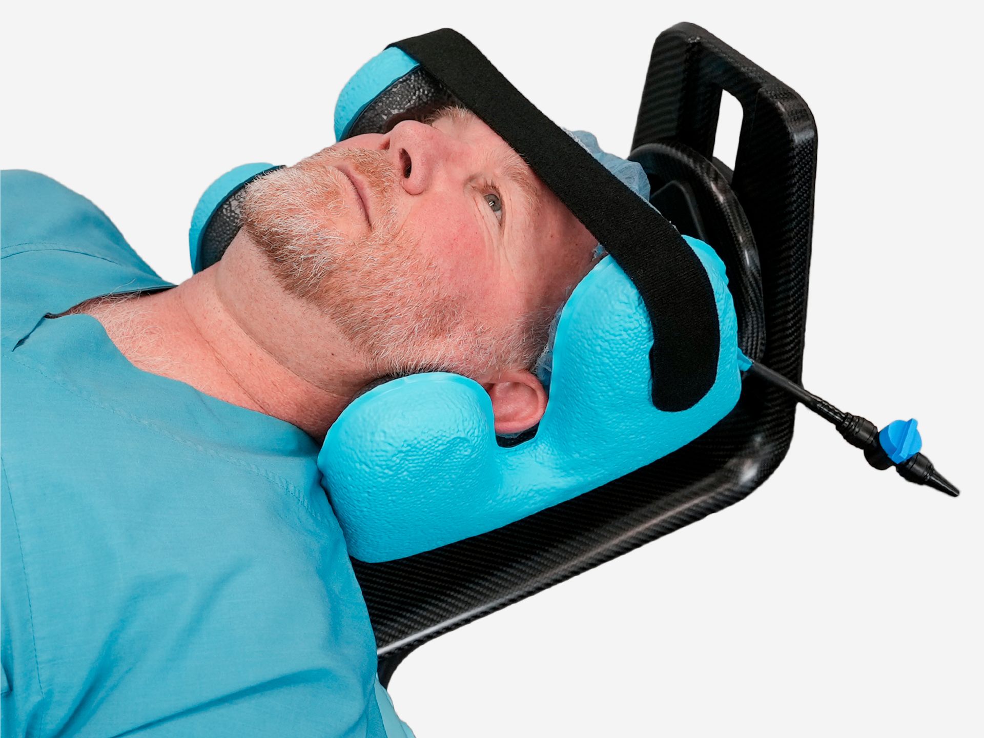
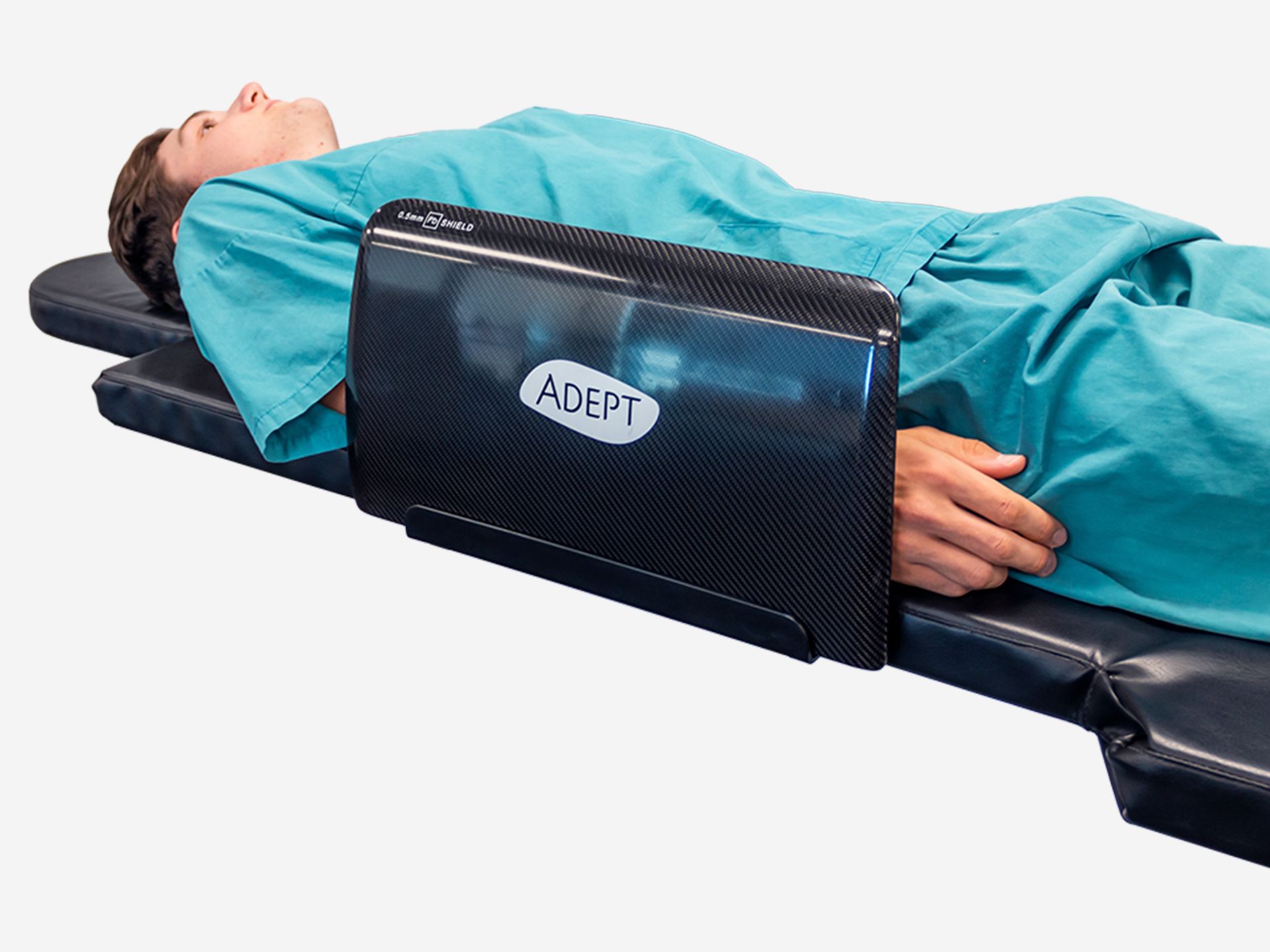
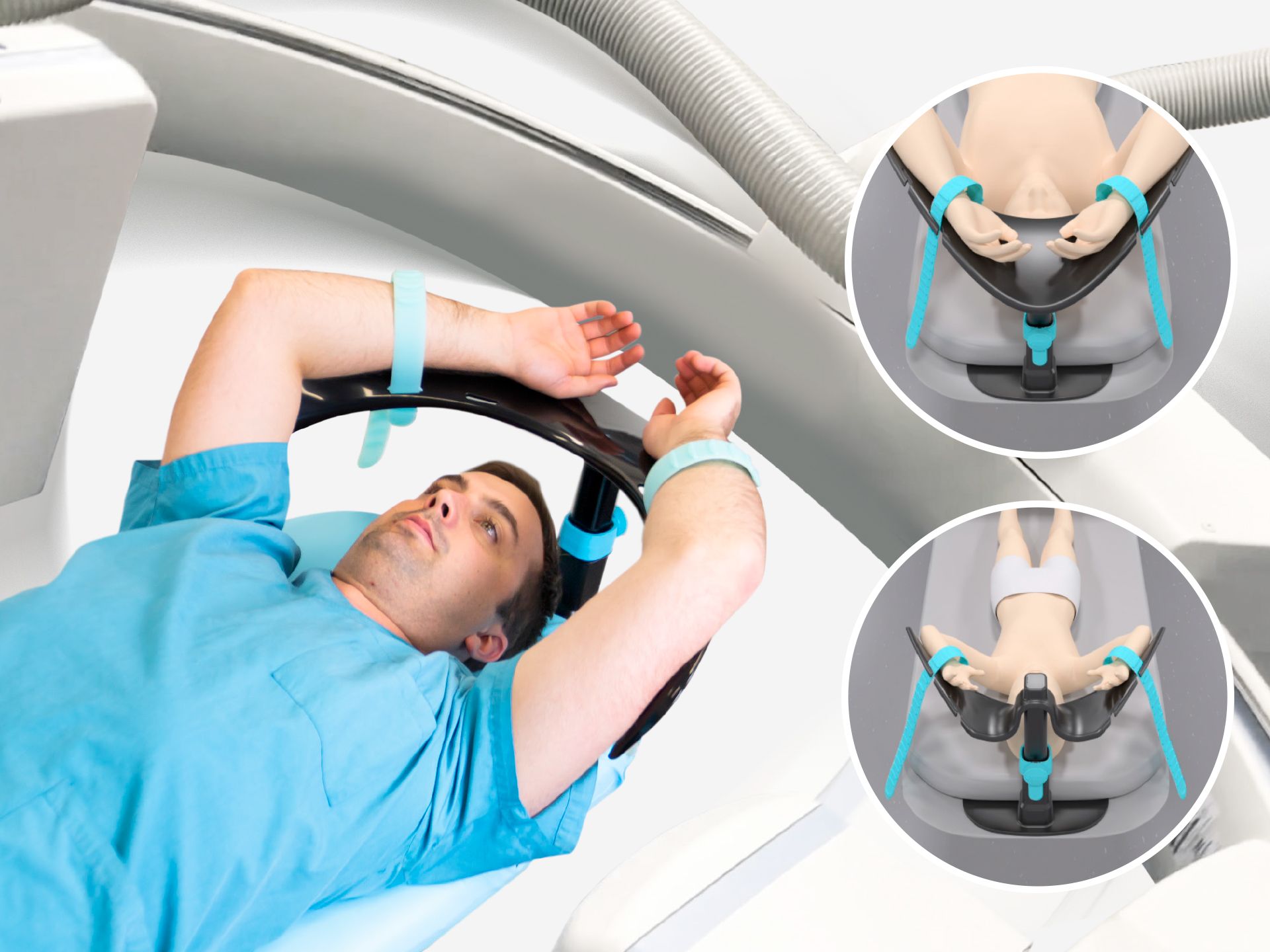
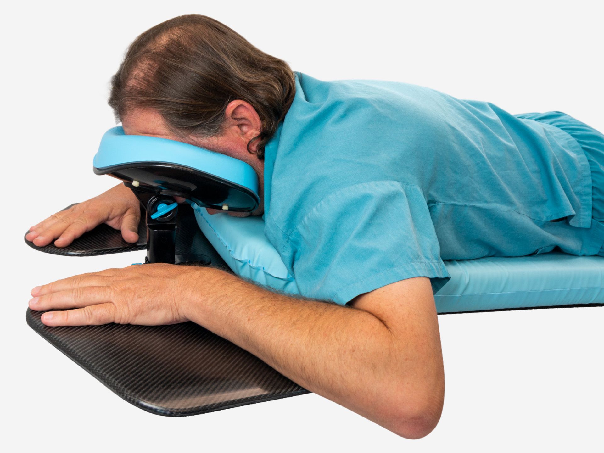
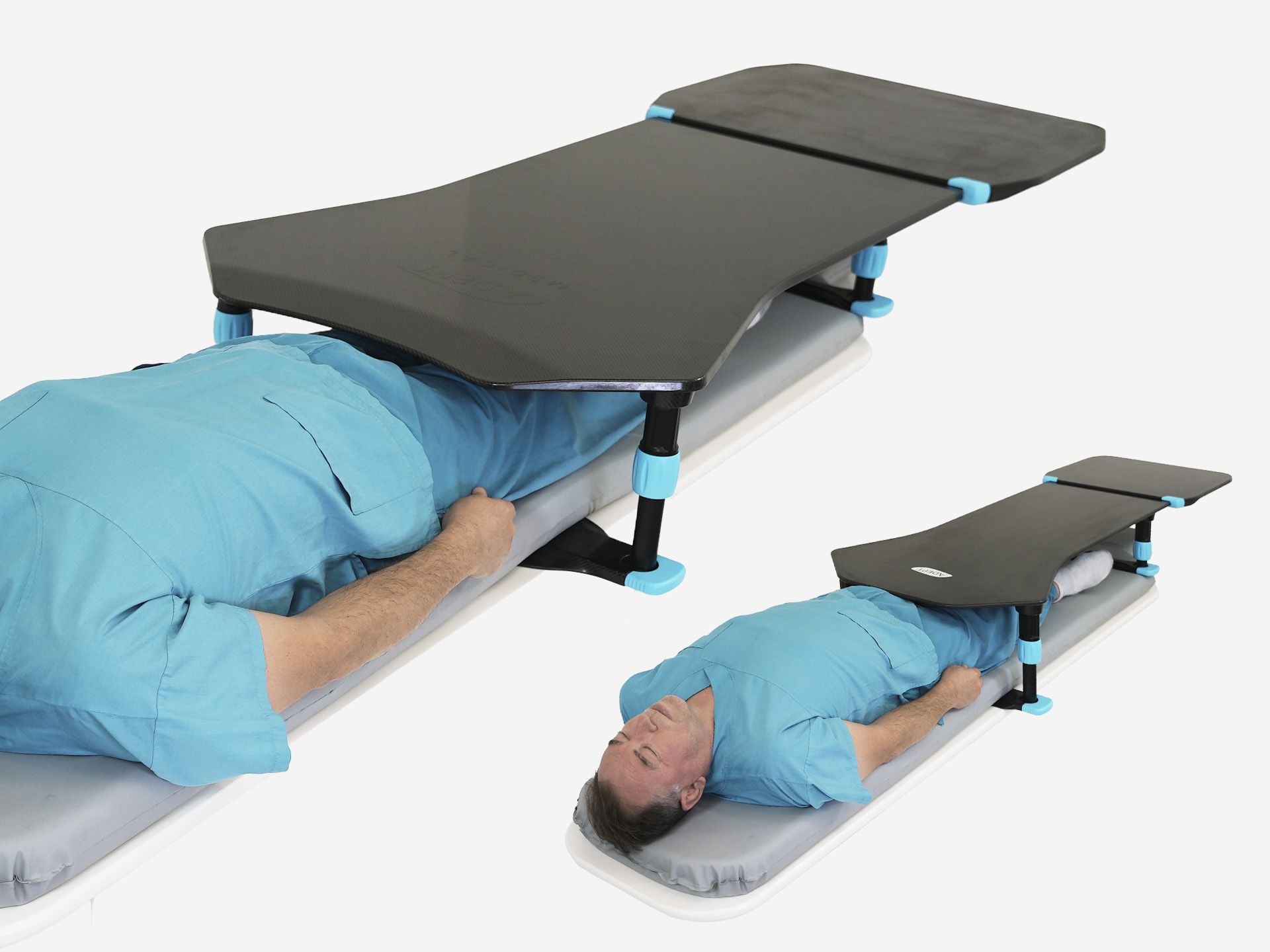
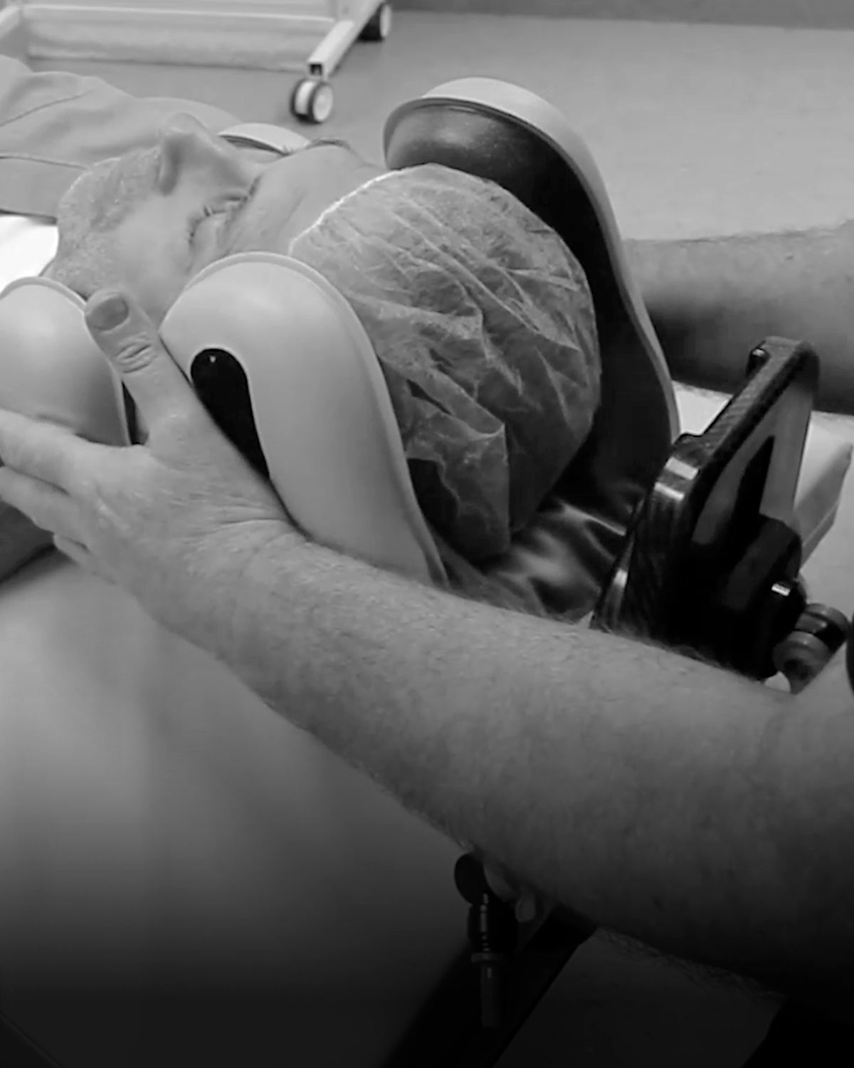
How to position the patient
Place the patient's head as close as possible to the leg assembly, with clearance between the head and the inside curve of the wing to avoid collision when adjusting the height.
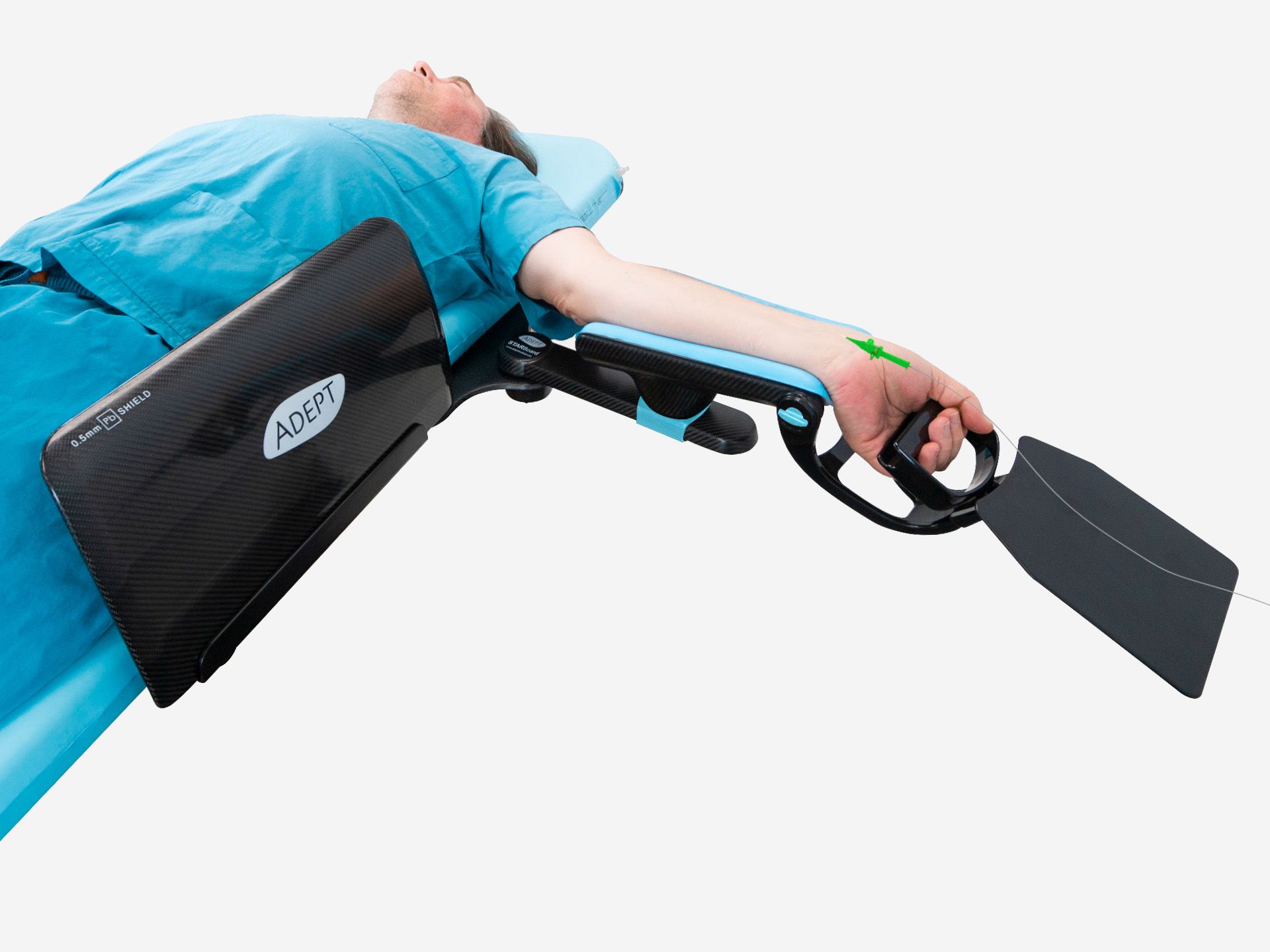
For the patient arms, the device will support one or both arms in the supine position, and a single arm when used with the posterior oblique position.
Take care not to over extend the patient's arms when placing in the overhead position. Do not use on patients with existing or or historical brachial plexus injury.
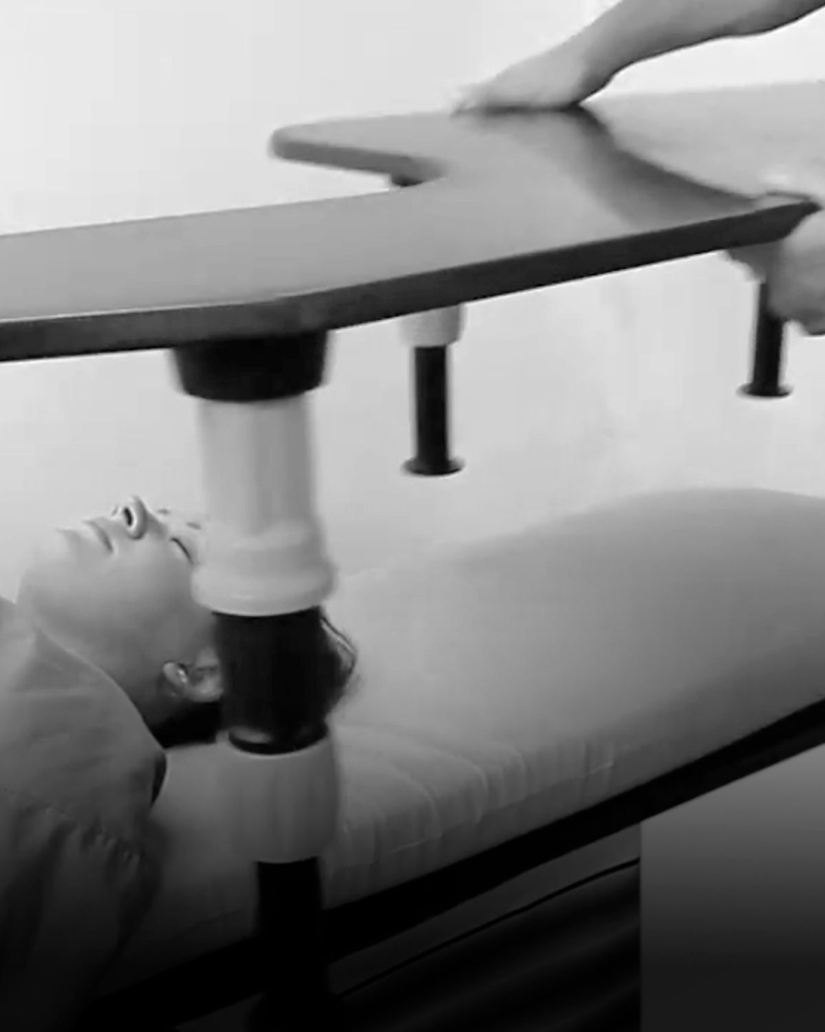
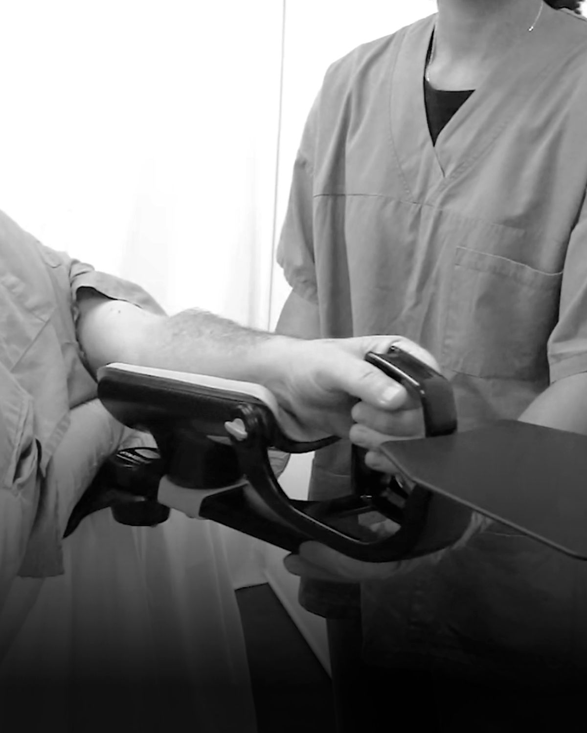
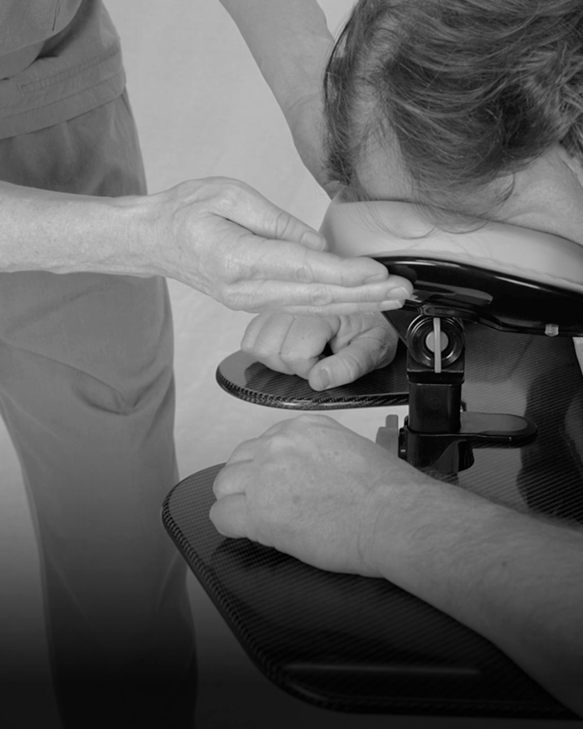
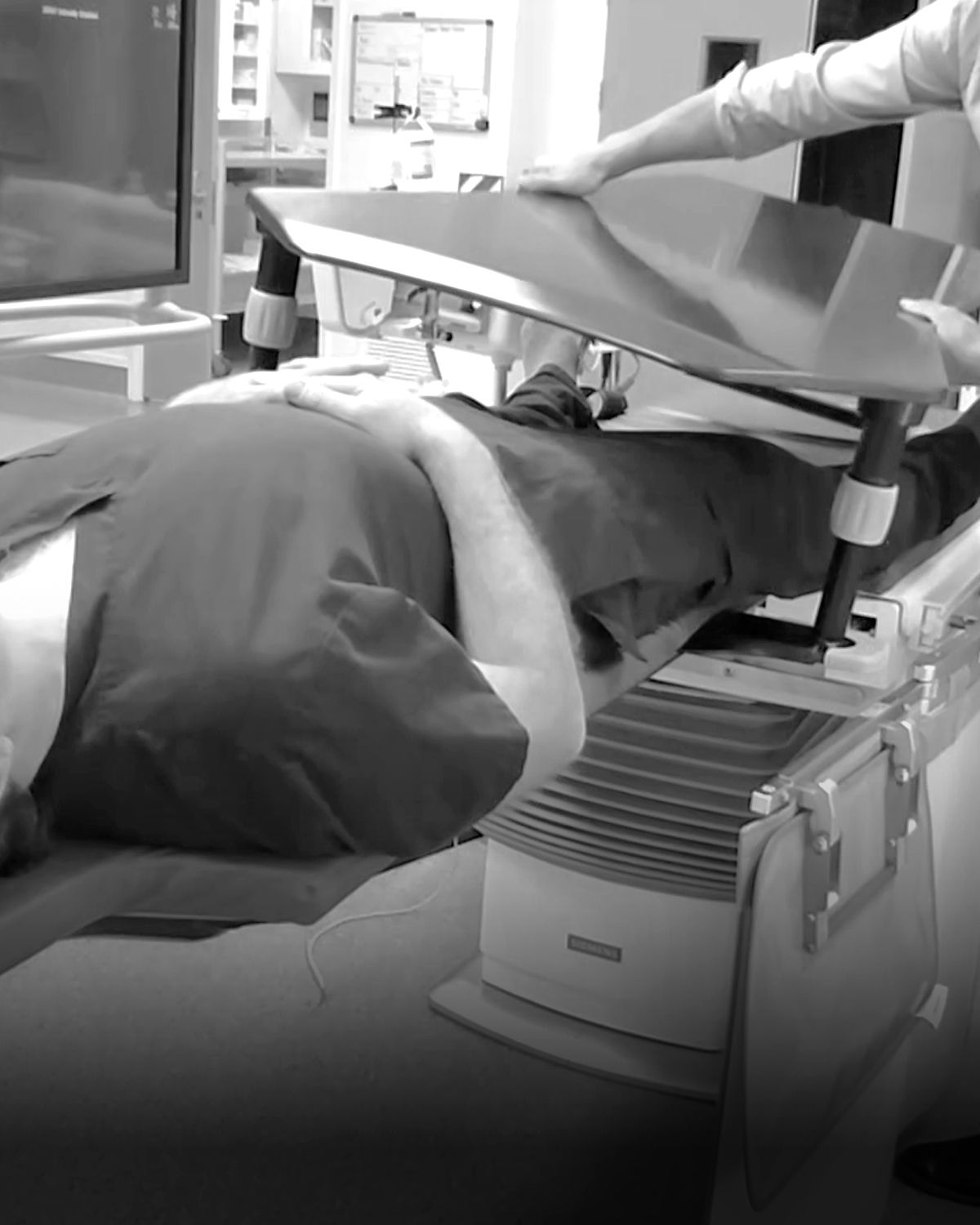
How to adjust the device height
Unlock the device by rotating the blue lever upward on the leg assembly. Allow the wing to rise for more height, or push down to lower. Rotate the blue lever downward to a vertical position to lock into place once you've reached the desired height.
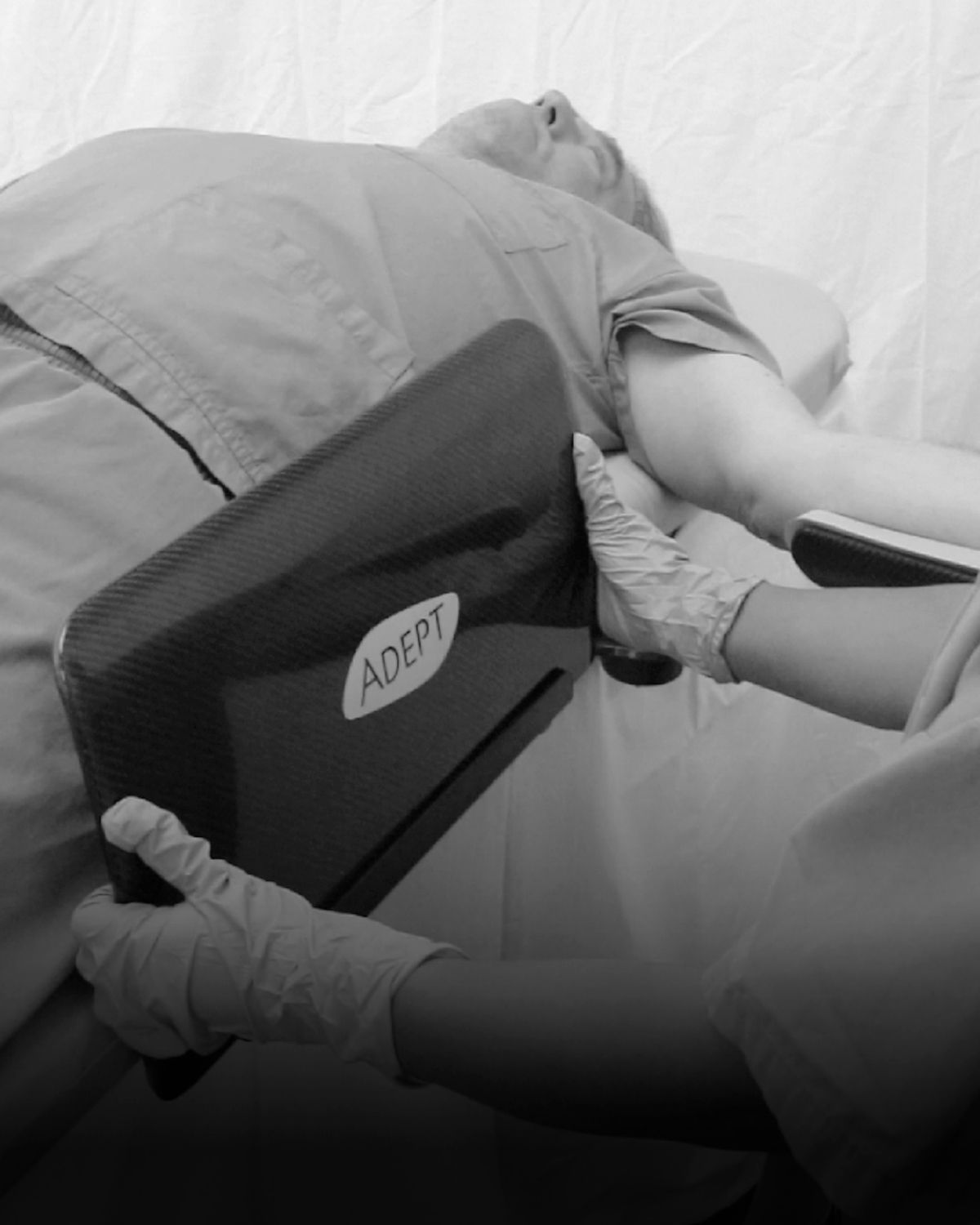
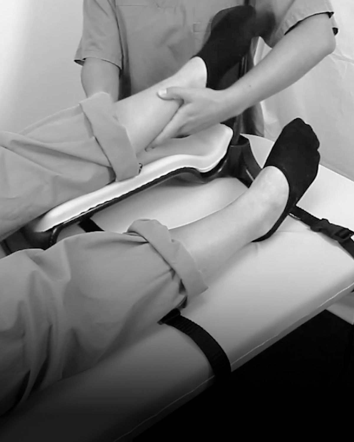
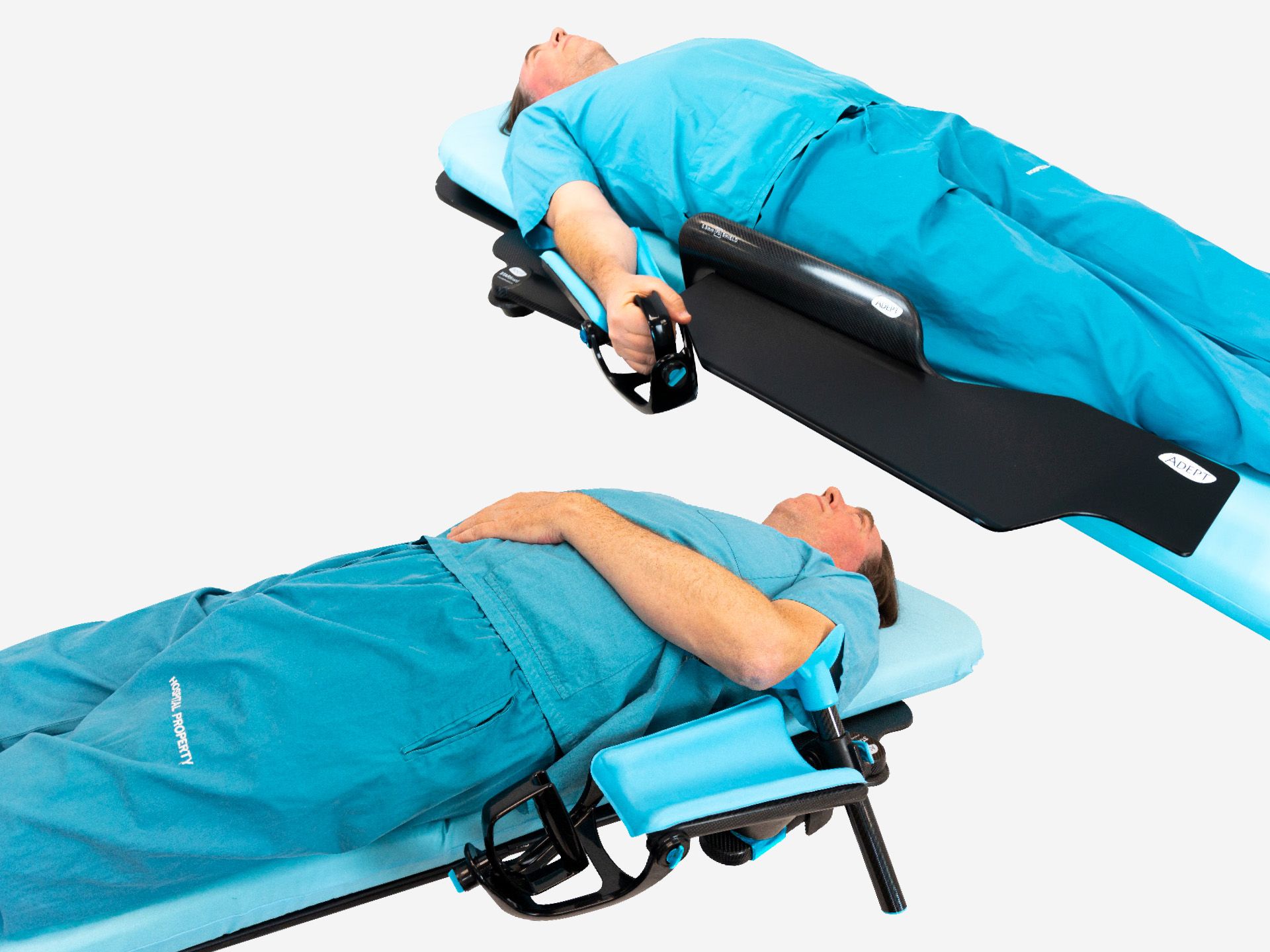
How to strap the patient's arm
For optional patient security and comfort, use the slots on the wing with the provided straps.
Insert the strap through the slot on the inner part of the wing. Ensure the ridges on the strap face away from the patient's arm for comfort. Pull the strap all the way through to ensure the patient cannot pull the strap out. Thread the strap over the patient arm and secure using the hook on the outside of the wing.
The strap is designed to loosely contain the patient's arm. Ensure that there is a 2-finger width gap between the arm and strap.
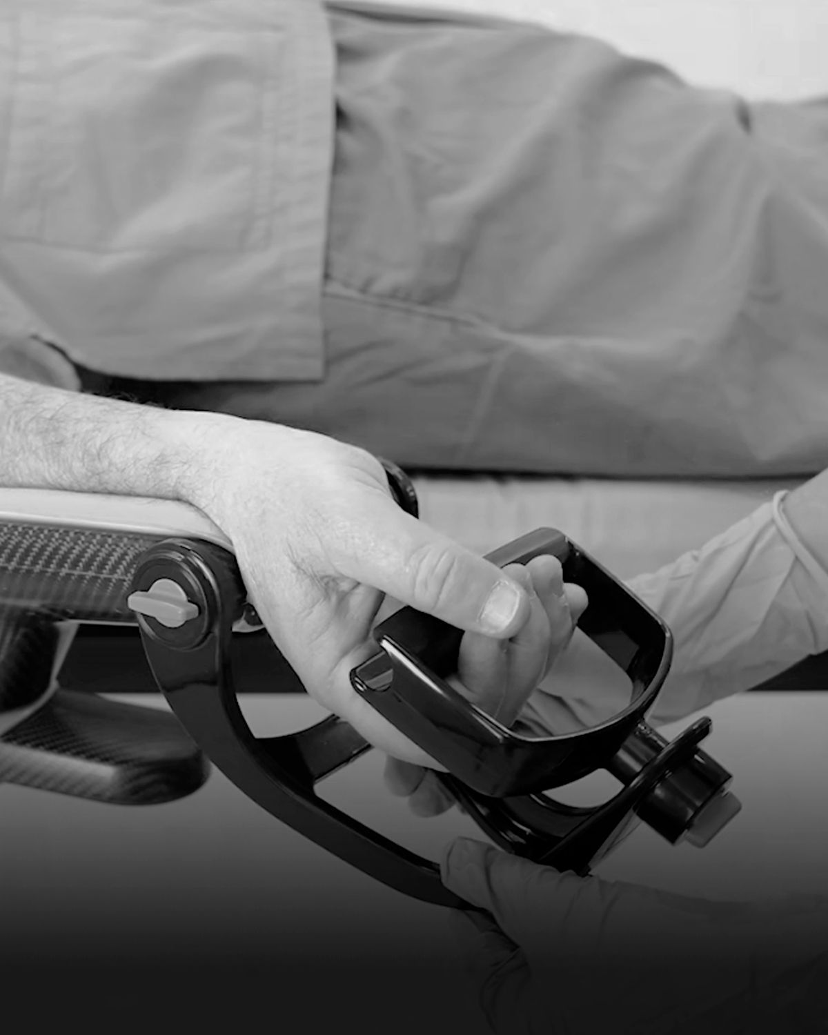
Strap placement options
The Overhead Arm Support offers multiple strap positioning options for your preference.
Straps can be placed close to the patient's hand for optimum patient safety.
If IV lines are present, the strap can be placed further towards the patient's elbow to facilitate IV-line access.
The device can also be used with no straps if there is no risk that the patient will dislodge during the procedure.
Padding placement (optional recommendation)
To enhance patient comfort and minimise the risk of pressure injuries, you can use gel pads or similar on the wing surfaces before positioning the patient’s arms. Secure with arm straps to ensure the pads stay in place and continue to offer protection throughout the procedure.
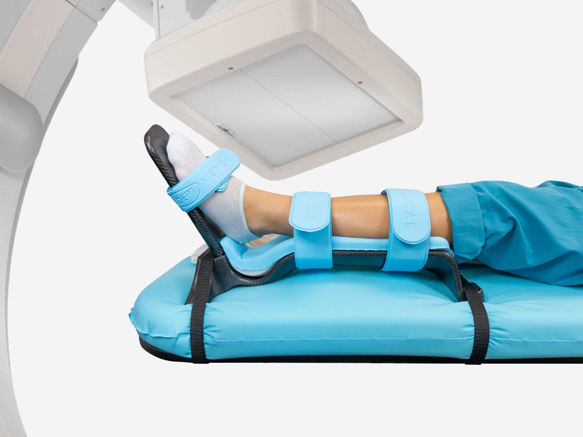
Ensure there is CT/MRI clearance
The product has been risk assessed to operate within the below specifications.
CT/MRI Bore:
AM4000: ≥ 700 mm
AM4100: ≥ 600 mm
Table Angulation: +/- 15° lateral & longitudinal
Table Surface: Flat / Curved
How to disassemble the wing and base
To disassemble the Overhead Arm Support, remove the wing by pulling it away from the Locking Leg. Then disengage the release clip on the bottom of the Base Board to detach the Locking Leg.
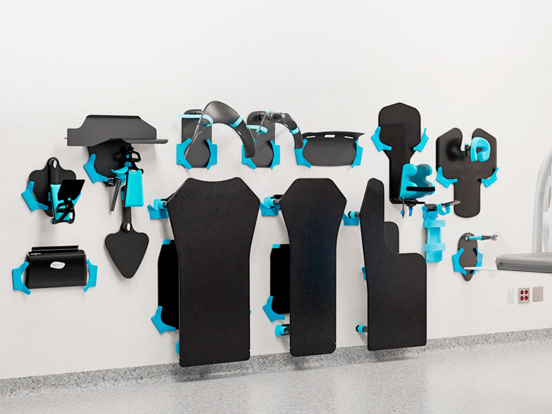
How to store the device?
For a simple hanging solution, use the Storage System, a custom-designed, space-saving storage solution for the Adept Medical suite.